Focus Fanatics Forum banner

DPFE sensor wiring pin-out...

30K views 11 replies 3 participants last post by  arlenn  
#1 ·
on my 2002 ZX, i am finding i have to replace the DPFE sensor, fine. Although it requires me to replace the electrical connector so i may accept the revised DPFE sensor... does anybody KNOW (not guess) if the wiring pin-out is the same? top=top, middle=middle etc.

Thanks in advance.
 
#2 ·
It's odd that you have a 2002 with the old sensor,

Image


New sensor,

Image


Some of the late 2001's already had the newer sensor but a few of the early 2002's had the old; all of the 2000's had the old though. So you have an oddball car, yay.

For some reason the Ford catalogs don't show this sensor and there has been rumors of it being discontinued. But you can try part # 4U7Z-9J460-AA,

Image
 
#4 ·
I picked up a "98BB-9J460-AB" and am trying to cipher the same thing. It's just a spare for me but want to know what I'd have to do to make it work if needed. I have the sensor as shown in the middle picture by 'iminhell' above.

Wire colors are different in the link you mention, op, also. But if we look at what voltage is in the harnesses mating connector, 5 volts on the outside pins, can we make a educated guess with damaging anything?

I'd rather know for sure too.
 
#5 ·
Per the wiring diagrams in Chilton 2000-2005:
(shown as a potentiometer/variable resistor)


Exhaust Pressure Transducer Sensor:

YEL/BLU wire goes to PCM (YEL) - Labeled "V REF"
BRN/BLU wire goes to PCM (BRN) - Labeled "RETURN"
WHT/BLU wire goes to PCM (WHT/BLU) - Labeled "EPT SENS"


Per FORD's diagrams the Exhaust Pressure Transducer (EPT) "B40","C705" sensor is a variable capacitor). (Unless I'm just misinterpreting automotive electronic symbols - I don't believe so.)

Pin 1 on EPT, YE/BU, goes to Pin 90 Powertrain Control Module (PCM), YE
Pin 2 on EPT, BN/BU, goes to Pin 91 PCM, BN
Pin 3 on EPT, WH/BU, goes to Pin 65 PCM, WH/BU

This is from, FORD, "Electronic Engine Controls" section and is shown as the same for either the 'CVH' or 'ZETEC'
on the 2000 year model.

We'd have to check later years and verify the transducer has the same internals and is a resistor and not a capacitor.

- While the server was down I checked the 2002 SPI (CHV) and the information for Pins 1 and 3 ARE switched.
- While the server was down I checked the 2002 Zetec and the information for Pins 1 and 3 were NOT switched.
FORD still shows the EPT (DPFE sensor) as a variable capacitor.

Methinks mistakes have been made........ either in the documentation or in the production/manufacture of the wiring/EPT/DPFE

...maybe if your swap doesn't work - swap pins 1 and 3. A potentiometer is just a voltage divide, a ratio of the voltage. So if the pins are swapped it is giving the PCM the wrong information, ratio. No biggie. What about other years 2001, 2003, 2004, 2005 - I can check 2001 also but then that's all the disks I have.

Or this could be why aftermarket DPFE/EPT makers give you three white wires and say "Good Luck".


my assumptions:

YEL = YE = Yellow
BLU = BU = BLUE
BRN = BM = BROWN
WHT = WH = WHITE

The internal circuit is a variable resistor/potentiometer and not an Early Pregnancy Test (EPT) or a Variable Capacitor.
 
#7 · (Edited)
forum is back up, yay!

ok, well i took apart the DPFE which is fairly simple... and they are NOT a simple transducer, a_2000_se; there is actually quite a bit going on inside them. The variable cap/resistor are probably functional symbols.

All the photos i have seen regardless of model, seem to to be wired white-brown-yellow starting from the top of the sensor; so i would assume that ford has did not change the pin-out from the old to new model.

Image
 
#8 ·
arlenn - do post pictures of the internals please. I'm curious what hardware is inside.

...."How are you defining pin 1/2/3?"....

Those are the reference designators that FORD uses on their schematics/documentation. Unfortunately they are not physically indicated on the case or connector. There must be some documentation for the connectors somewhere that indicates 'Pin 1' Maybe the manufacturer of the mating connector? Or you could use the wire color codes to determine this:

From FORD wiring diagrams:

Pin 1 on EPT, YE/BU, goes to Pin 90 Powertrain Control Module (PCM), YE
Pin 2 on EPT, BN/BU, goes to Pin 91 PCM, BN
Pin 3 on EPT, WH/BU, goes to Pin 65 PCM, WH/BU

(possible exceptions and ambiguities noted earlier)

I found a good source of info on the EGR system from another site while this site was down and am posting it under a new title: "EGR. Everything you wanted to know about,"
 
#10 · (Edited)
BIG thanks a_2000_se for your research in this DPFE sensor swap ordeal...

I swapped it out tonight, things went very well, and the DPFE pins to seem to match directly; (i found a collapsed PCV vacuum line while poking around with the repair though).

*ran very well last night... not so much today... guess its not DPFE... keep looking :(, maybe the PCV will help something *
 
#11 ·
Thanks for posting the picture of its internals, another mystery solved. Good job on getting the case apart without damaging it - was it as easy as just prying it apart?

It doesn't really matter at this point since you've got the information you were looking for but the I.C.'s on the circuit board - do they have part numbers on them that could be looked up to see where the power/ground pins are? Or are they proprietary? If the need arises again the pwr/gnd pins could be ohmed out to the edge connector. It's almost a gimme that the beefed up pcb trace in the center would be ground.

...ok - what else can we take apart ...............
 
#12 ·
the replaced PCV hose seems to make all difference in the world, it was a fire breathing dragon tonight.

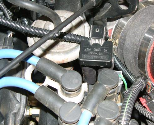
it was very easy to take apart two tabs hold the back on, and the insides were potted with some clear goo.

i am going to bet that the ICs are amplifiers. but im not going to remove the device and check it out, you can open yours :p Opening up the device an seeing what appears to full of amplifiers, the ohm meter reading are pretty much useless, and would explain the 160kohm readings which is almost an open circuit.

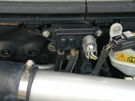
As we are only dealing with signals we are not going to need a beefed up ground. i don't think the device has a typical ground, as from your diagrams, the pins are: DPFE, signal, vref; and you measured 5, 0, 5 vdc respectively. i am sure we are sinking though the ECU. vref kinda hints to a comparator circuit of some kind (remember the op-amp circuits you build in high school?)

i installed as per your diagram which agreed with the wiring of the original device. getting tired of the car running like crap, i ran with that and installed the device; after my little hiccup with the PCV it would appear that everything is ok.

your research helped a lot and it and it would appear that ford stayed pretty consistent with design of the sensors (i would not make any sense to give a mechanic grief when ford service is bluebook pricing) i feel the device is installed correctly, the computer is happy and the car is running the best it ever has (tonight), i bought it used.

cheers!

now that the stumble is sorted, we can concentrate on more important things... like go-fast parts.