Focus Fanatics Forum banner

Project: In over my head

13K views 131 replies 14 participants last post by  jordanm1983  
#1 ·
Ok, so i have this project in my garage. Im am no where near being an engineer, so this is a place to gain some knowledge.

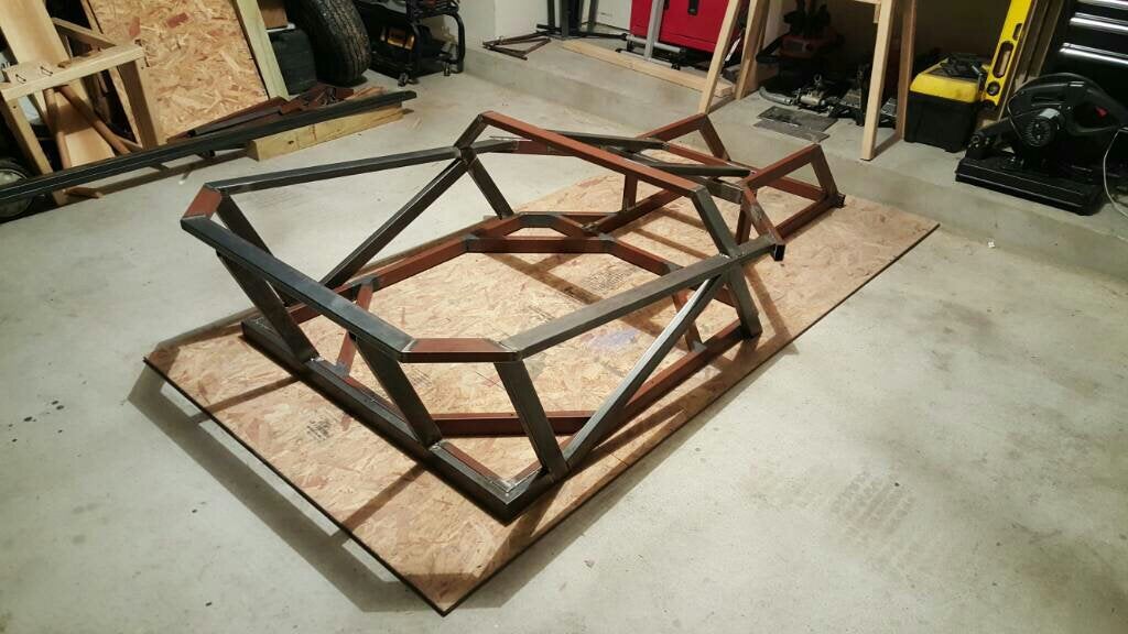
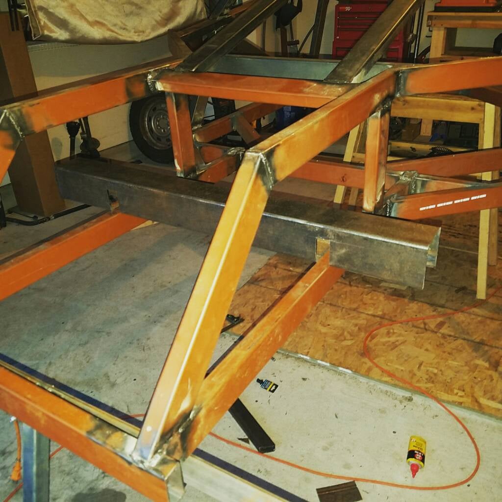
So far I have a custom built chassis out of 11g 1x2 rectangular tubing.
Image


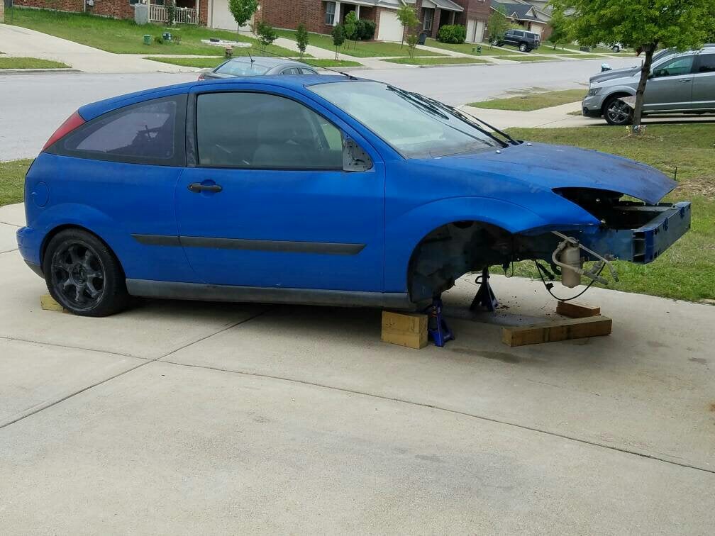
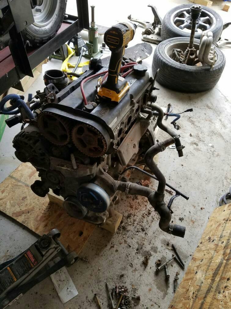
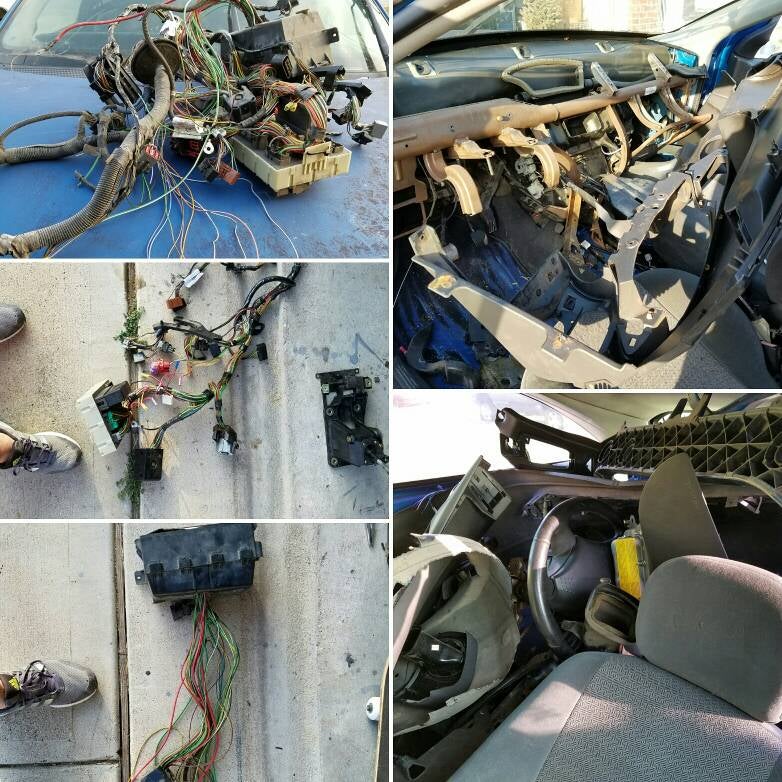
Scrapt a 2000ish focus ZX3 for the driveline and various other parts that i am finding out are more useful than scrap.
Image

Image


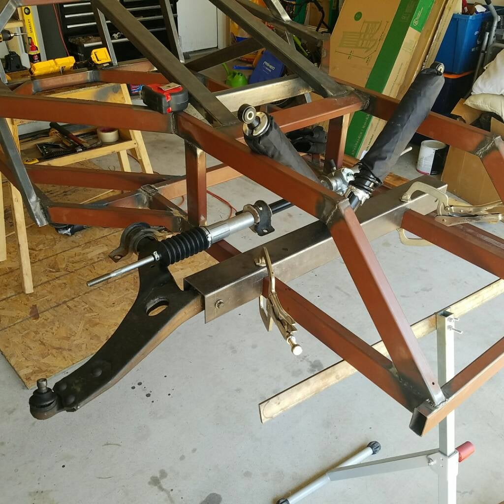
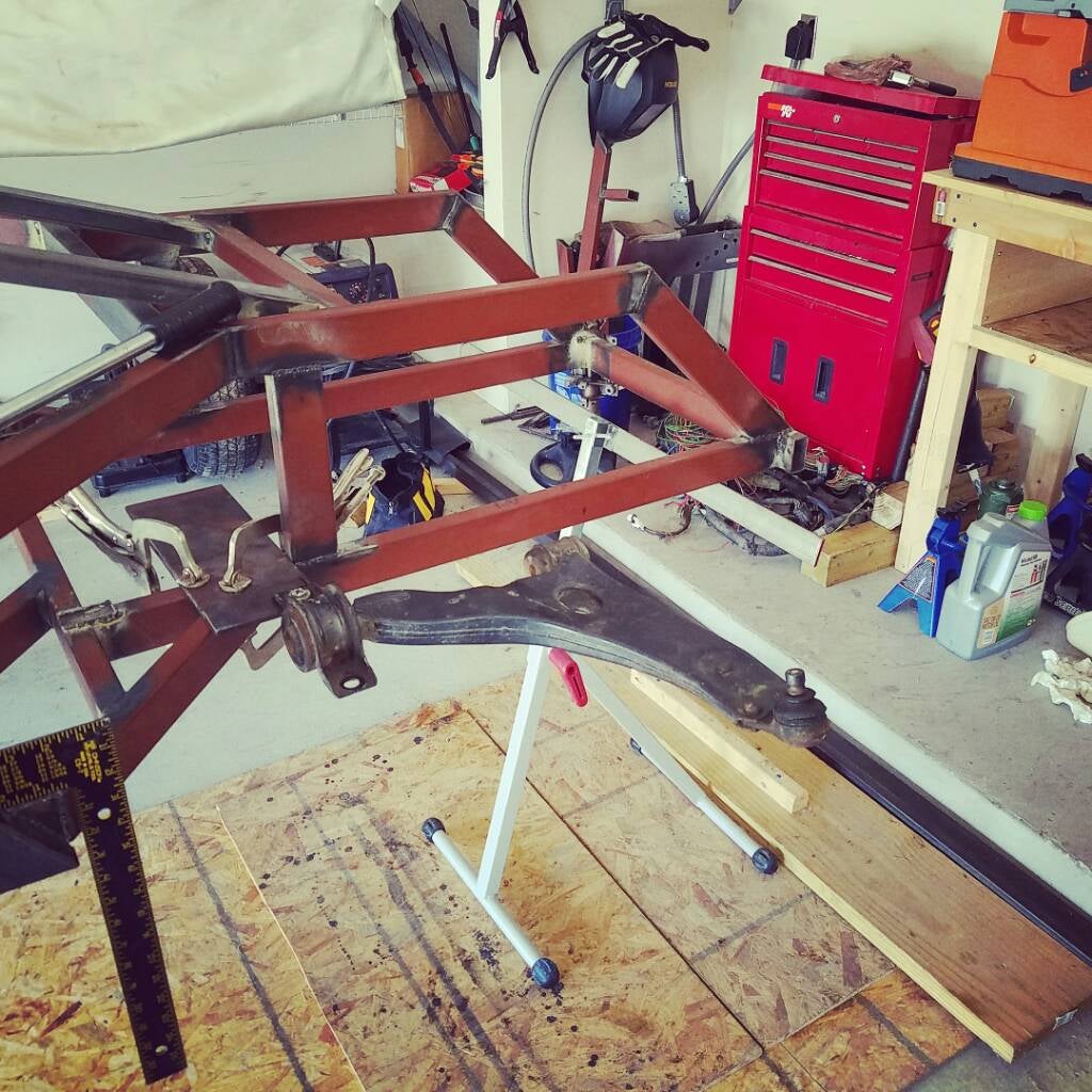
Ive currently made the decision to use as many parts from the car as possible and have spent what little time ive been able to work on the car at the front end.
Image

Image


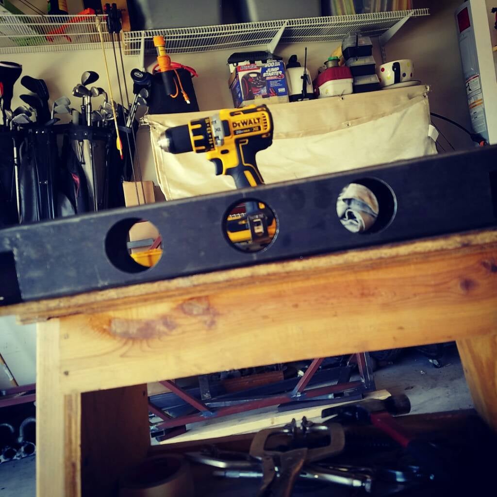
And some random photos
Image

Image
Image


Sent from my SM-G930P using Tapatalk
 
#3 ·
Alot of respect taking on a full custom build first time out. But!.... what are you building it to do?
 
  • Like
Reactions: pasta
#8 ·
Daily driver? Street toy? Weekend trail rig? Autocross? Sand buggy? We understand you want it street legal just curious the overall purpose of the build?

I live in South Georgia. I understand easy street legal. Down here four wheels, seat belts and blinkers (optional but recommended) will get you a A+ on inspection and a title. lol
 
  • Like
Reactions: smallblockfever
#9 ·
Its a learning experience. Thats its true purpose. I saw an Ariel Atom and told myself i could build that.

My original thought was to put an A- arm suspension up front but found our my steering rack was 29" from pivot to pivot requiring me to make my front end 9" wider. Now i have this 3x3 chunck of metal upfront to widen the front end and that is how it sits.

Sent from my SM-G930P using Tapatalk
 
#11 ·
Its gonna be a 2 seater, but I haven figured out how I wanna have it layed out. Was thinking of just having a single bench seat (like you would see in the back of a mustang) with separate back rest. All sitting on sliding mounts.

Sent from my SM-G930P using Tapatalk
 
#13 ·
Got a little more work done before i had to get cleaned up for the kids soccer game.


Cut the ends of the A-arm mount down to fit the focus a-arms and alow them to flex. Also took some of those circles I cut out and welded them to the inside as spacers for the a-arms.

Now I need to get some 3" x 3/16 cold rolled steel and fab it up to support the rear portion of the a-arm.

Image


Sent from my SM-G930P using Tapatalk
 
#17 ·
Well, its not finnished. I ran out of time before life kicked in and I had more important things to do.

And how is that upside down. Thats how they sit in the car.

Sent from my SM-G930P using Tapatalk
 
#18 ·
Looks like the orientation is correct. That's the right side?

But what are you going to do about the other bolt on the rear bushing mount? I'm just asking.

Welds look decent tho.
 
#20 ·
Was thinking of running a piece under the frame running the length of the two ends.

My welds suck, but im slowly figuring this welding thing out with the help of youtube.

You can actually see my begining welds behind the better ones.
Image


Sent from my SM-G930P using Tapatalk
 
#21 ·
Not trying to be critical, fun big project.

Just hope if we notice anything odd it might help in figuring out the fabrication before it gets finalized.

The clamp that is attached to the outer cylinder for the bushing at the rear of the arm bolts up from underneath normally, and the top side of that cylinder fits into a recess in the frame to cradle the other side of it.

Can't see your fits & angles precisely from the pictures, but I think if you flipped it over before putting the cross bar mentioned on the top you could notch the bar for a curved piece made from flat stock bent to match the bushing shell to make something similar.
 
#22 ·
^^^^^^ I agree. Try to keep the mount point as close to the factory as possible. We are no engineers and it's probably built that way by Ford for a reason.

Looking forward to seeing the progress.
 
#23 ·
Well, I was going to keep it in its factory position until I was messing around with the a-arm and after enough torque I could get the rear to spin inside the housing.

And a better look at the housing.
Image
Image
 
#24 ·
Shucks, all that means is that it was rusted on tighter in the center than pressed in at the outside. Stock bushing does have an orientation you want to maintain. What if you can't spin the other one or some day need to replace one? (arms come with bushes when replacing them for new ball joints)

I still prefer the idea of cradling the open side like stock so the U-Clamp holds it in compression when installed. The tack welds from clamp to sleeve are just there to keep it in position as a single piece, not take the full suspension loading. (Mild compression, there isn't space between clamps and frame when tightened up)
 
#26 ·
I still prefer the idea of cradling the open side like stock so the U-Clamp holds it in compression when installed. The tack welds from clamp to sleeve are just there to keep it in position as a single piece, not take the full suspension loading. (Mild compression, there isn't space between clamps and frame when tightened up)
Up to you, I can't see a gap all the way around on the sub frame side or if it presses inwards harder when the suspension takes a load and the clamp flexes.

All I know is that cradled for 360* even if not touching at all of them is more secure than hanging off a tab or two and a couple tack welds. Stock mounting is firm enough to let the arm bend before the mount breaks loose if the wheel gets hit. Seen arms replaced after collisions/curb hits without anything else damaged other than a tie rod.
 
#27 ·
There is a goog 1/4" gap between the housing and sub frame. Doesnt look like they were worried about movement other than the rotational forces while the suspension flexed.

Sent from my SM-G930P using Tapatalk